

Gulbransen Player Piano
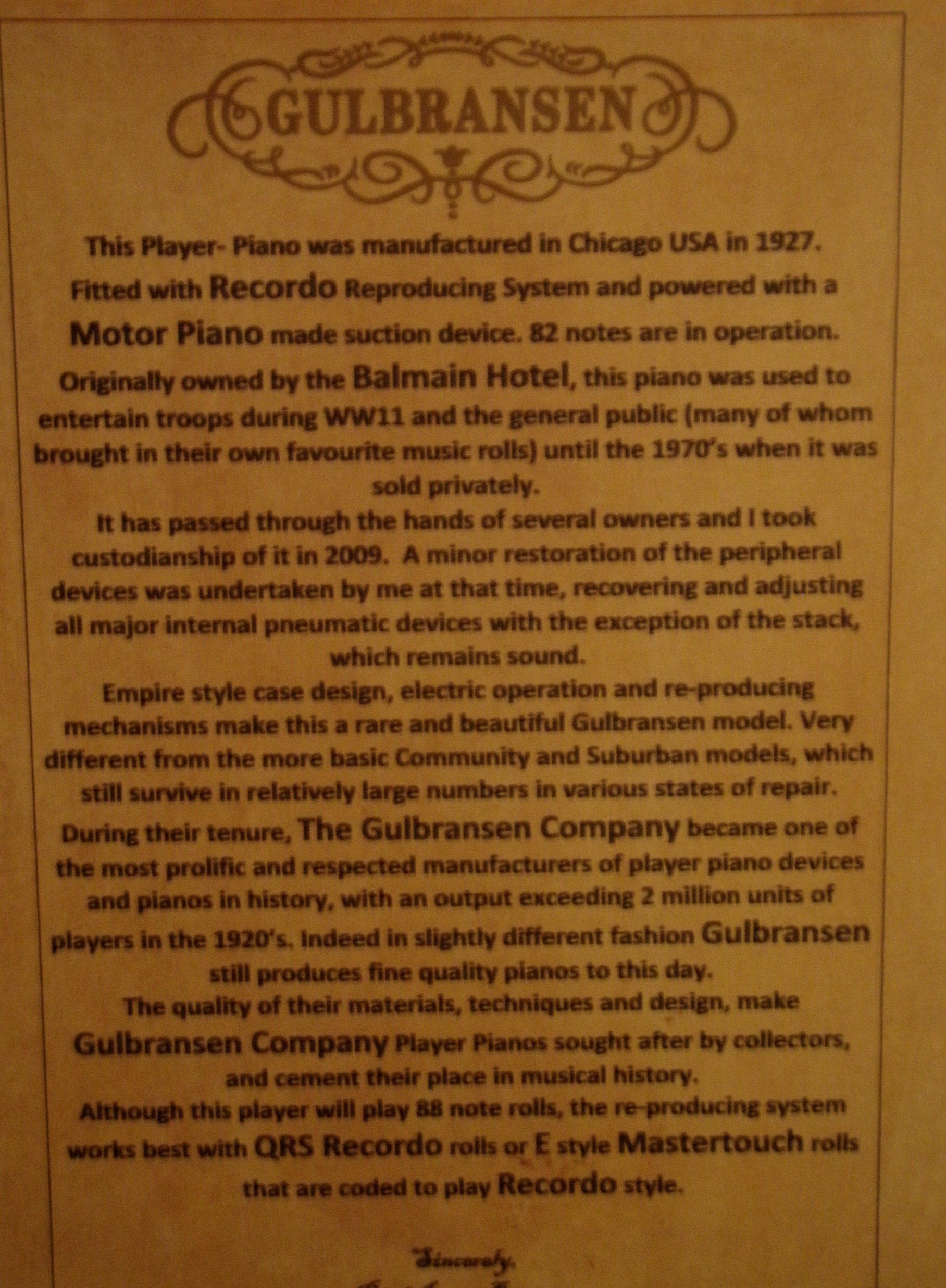
Arguably the most successful, certainly the most prolific manufacturer of player pianos in history, the Gulbransen Co. mass produced player pianos in Chicago Illinois. Established by the innovative Axel Gulbransen in 1904, by the late teens Gulbransen was the largest player piano manufacturer in the world. The Gulbransen 'Registering Piano' and trademarked 'Easy to Play' baby logo, was one of the best known brands of it's time and one of the best known trademarks in the world.
Gulbransen pianos were well built and high quality despite being produced en mass. The player system utilizes very small channels in the pneumatic board to minimise the suction required to run the player pneumatics, this allows a minimal pedalling requirement to achieve full sounding music. With a well restored Gulbransen player, you may literally feel each note play through your feet on the treadles. If there were awards for efficiency, the Gulbransen would win hands down.
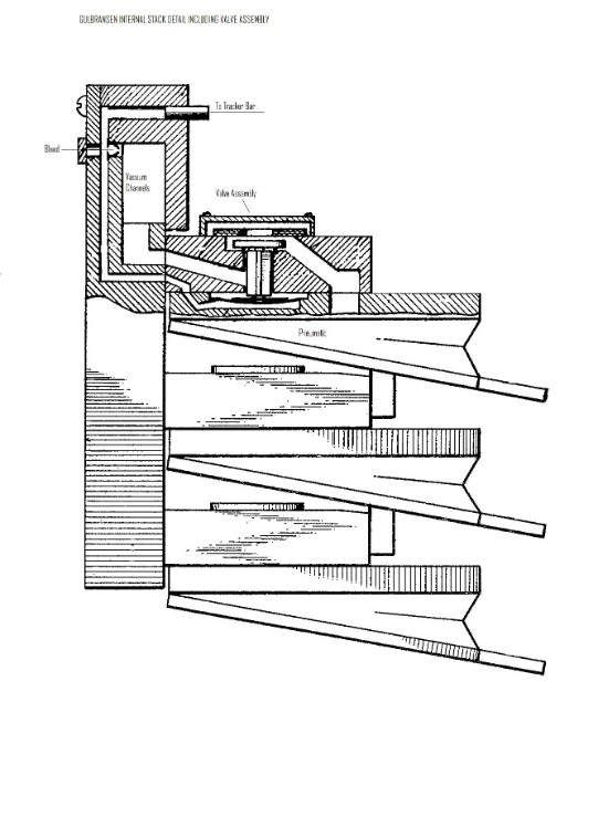
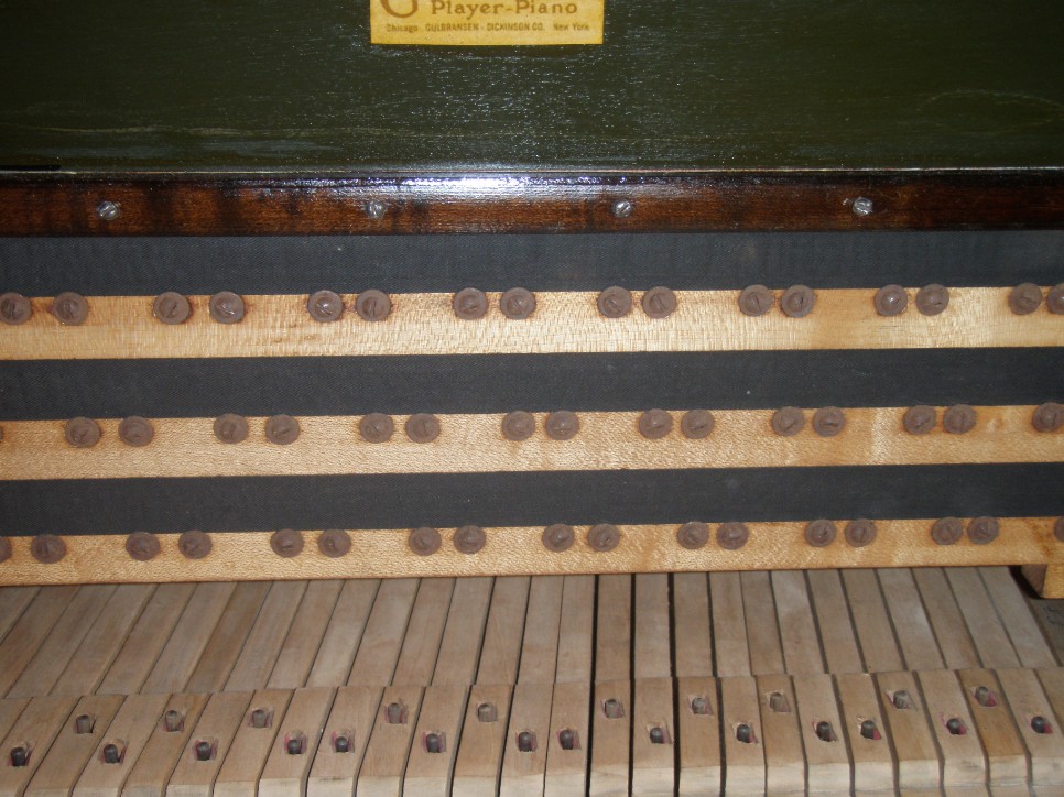
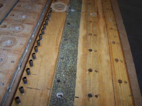
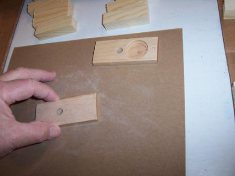
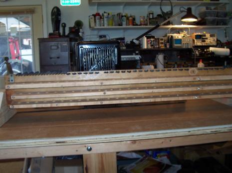
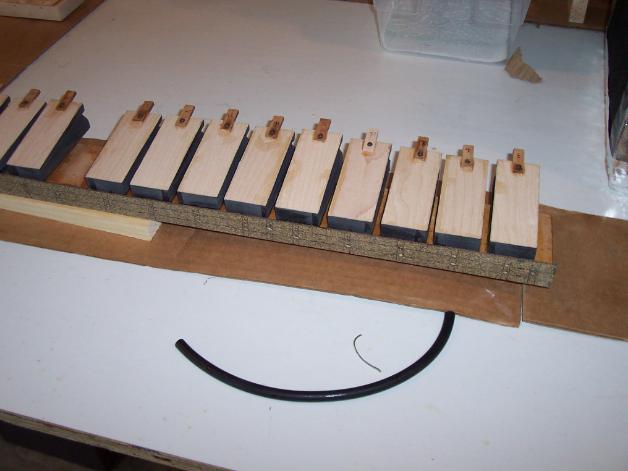
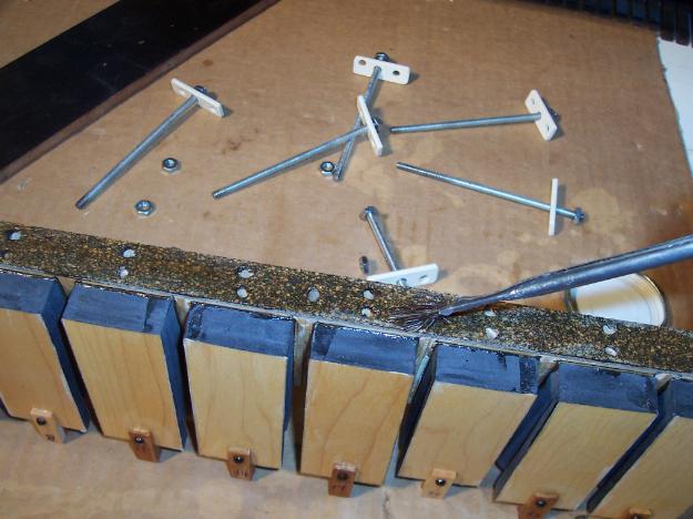
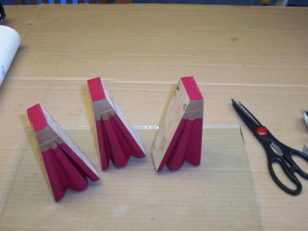
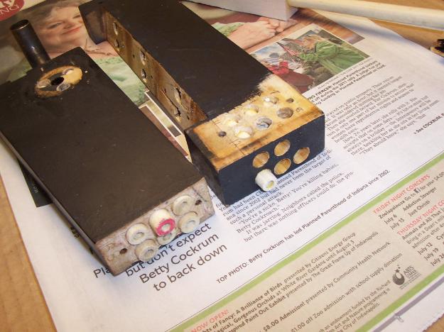
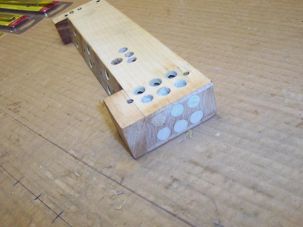
Originally each of three pneumatic boards (housing the valve assemblies) were glued to the vacuum chest and while this made for an extremely airtight stack, it was and is equally difficult to separate and repair. These glued stacks may be recognised by the lack of screws on front of the pneumatic board and are not recommended for inexperienced restorers. When a stack was returned for service during the 10 year warranty period, the faulty stack was burnt and a brand new stack delivered to the customer. Later stacks have unit pneumatics screwed to the chest and are easier to restore, bearing in mind that each unit must be split in order to effect replacement of valve faces, pouch, and recovering of the pneumatic. This screwed unit pneumatic system, was introduced as far more cost effective from a service point of view, as one single faulty pneumatic could be easily replaced and did not necessarily condemn the entire stack.
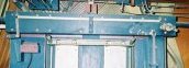
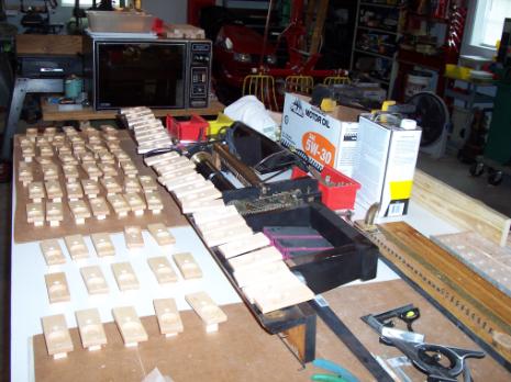
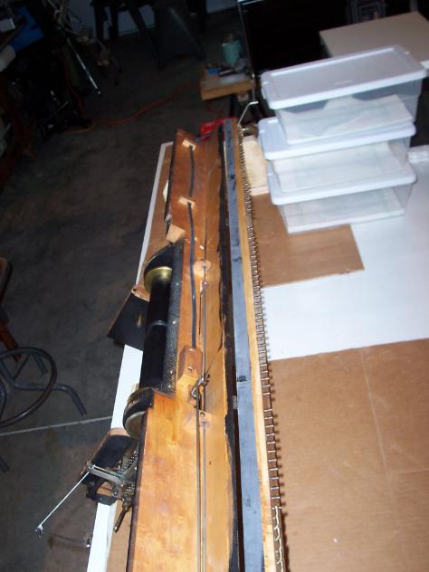
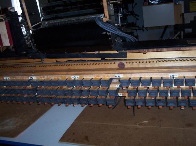
In fact, an economy of all the player systems were effected by Gulbransen. The foot pump is small in comparison to similar systems and controls such as the motor governor and rewind stack shut-off pneumatics, are attached directly to the wind chest. All directly attributed to the restriction of vacuum channels, as previously mentioned. The wind motor is a compact three hinged double pneumatic unit with rotary valve to open and close all three double pneumatics. It works smoothly and with a slight 'chugging' sound as the valve works.
Gulbransen Stack Cross Section

Stack To Piano Action Position

Screwed Stack Detail - later Gulbransen Stack (circa 1928)
Behind the strip of polished wood,you will find the pneumatic bleed cups, these need to be clear of dust and debris in order for the stack to operate correctly, the bleed channel is under stack suction when the machine is playing. Blocked bleeds can cause a lack of repetition, slow operation of the pneumatic or a silent note. Be careful when cleaning the brass bleed cups, that you do not enlarge the bleed hole. Usually the strip of leather seal on the bleed cover will need replacing. The vacuum channels reside behind the three strips of black pneumatic cloth between the rows of screws.
Gulbransen Tracker Finger


Two internal views of the Gulbransen tracker finger assembly. Left photo; as seen from above. Right photo; side view

If your Gulbransen is playing notes when set to rewind, it is likely that the valve controlled by the stack shut off pneumatic (the small pneumatic on the left side of the pumping bellows), is not fully closing the valve inside the trunk, allowing suction to bleed into the stack. This may be adjusted easily by holding the pneumatic closed, loosening the linkage set screw, pushing the protruding valve arm left to fully closed then tightening the set screw. This can be achieved without opening the trunk. If it continues to be a problem, the internal valves may be rotten and would require re-covering. The trunk face may be opened to access the valves by removing the linkages, disconnecting the right side external governor valve and unscrew 12 screws on the forward face. The face board is gasketed for air tightness with leather gasket strips. These gaskets must be renewed when re-assembling.

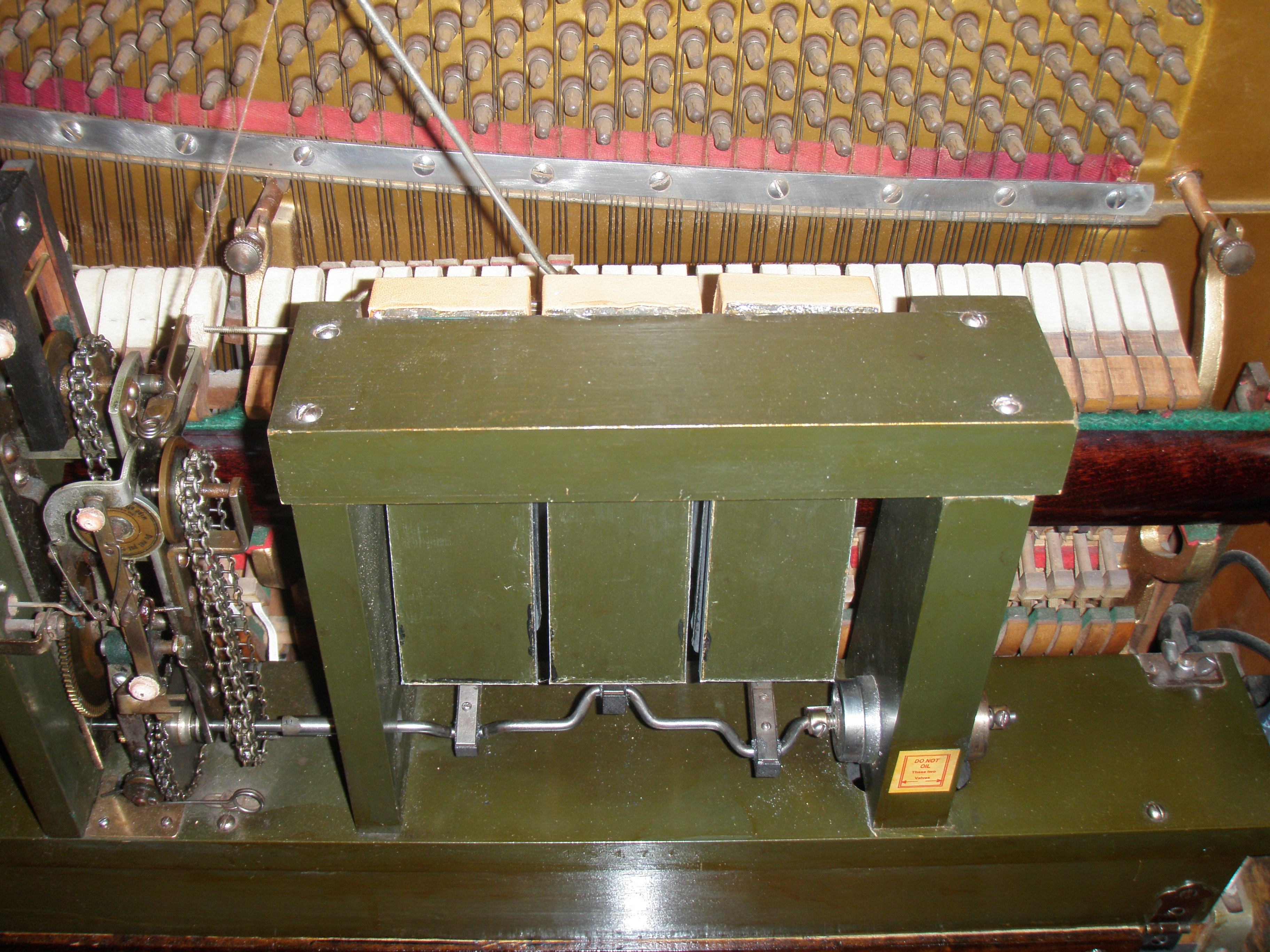
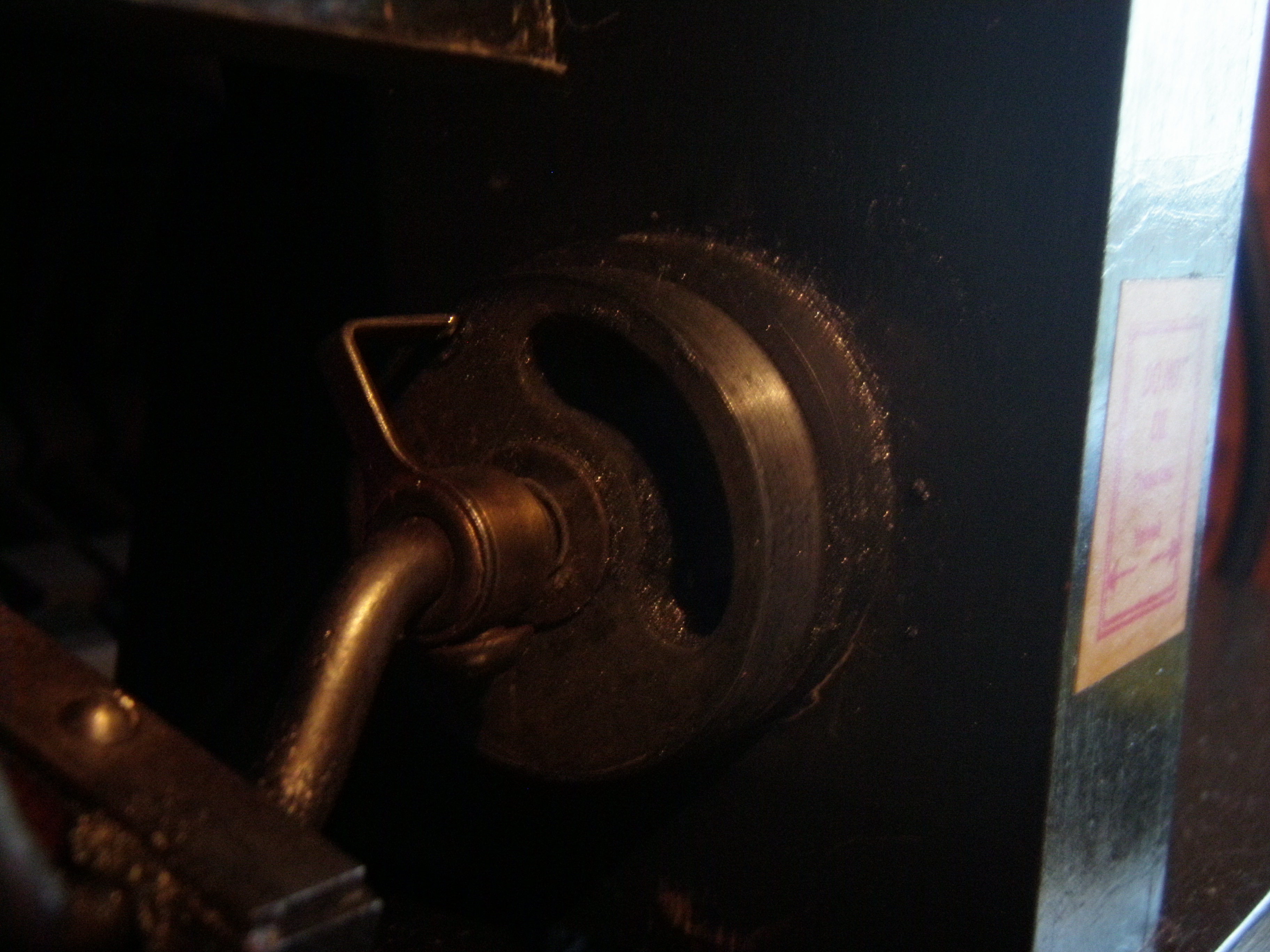
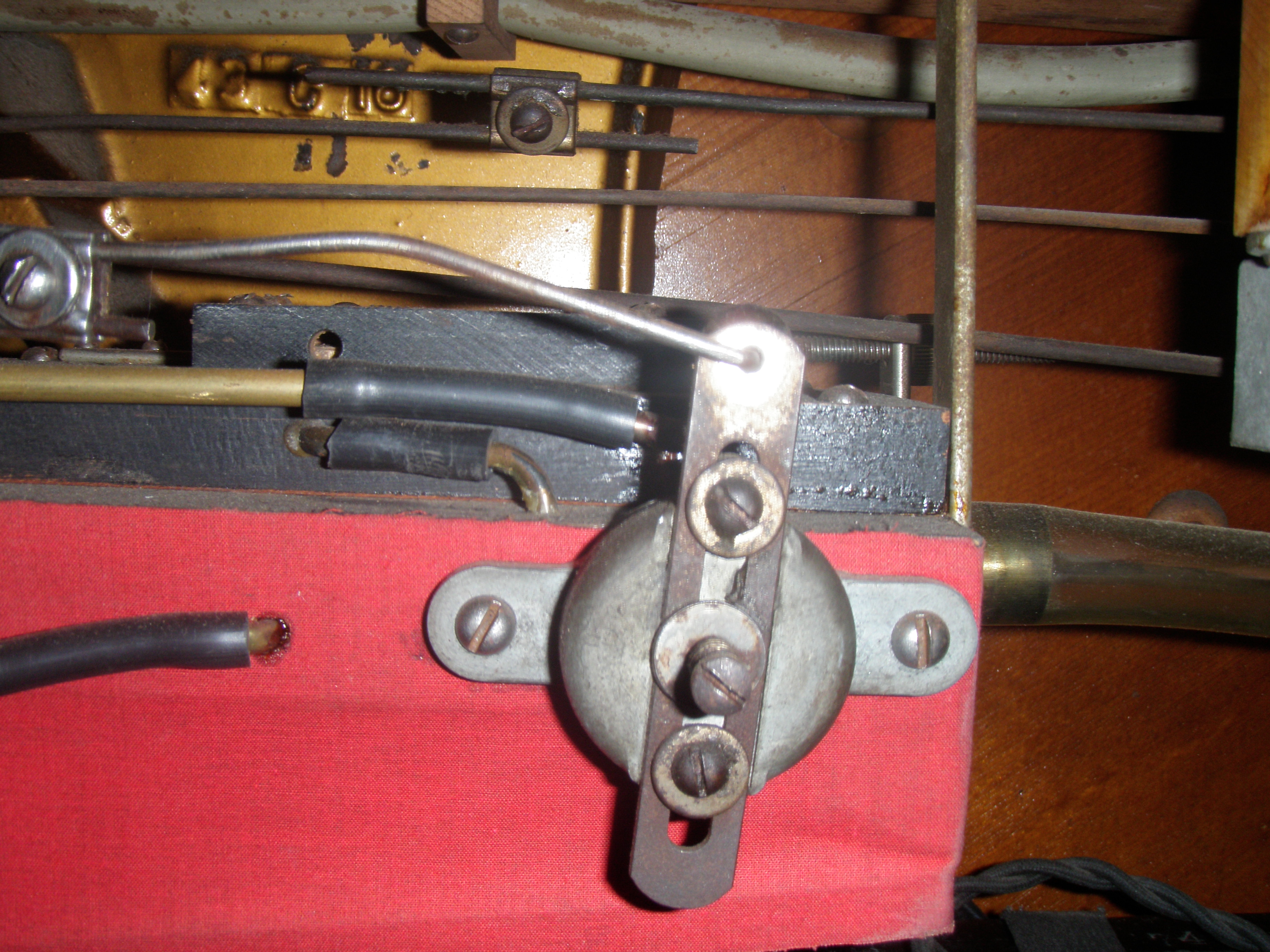
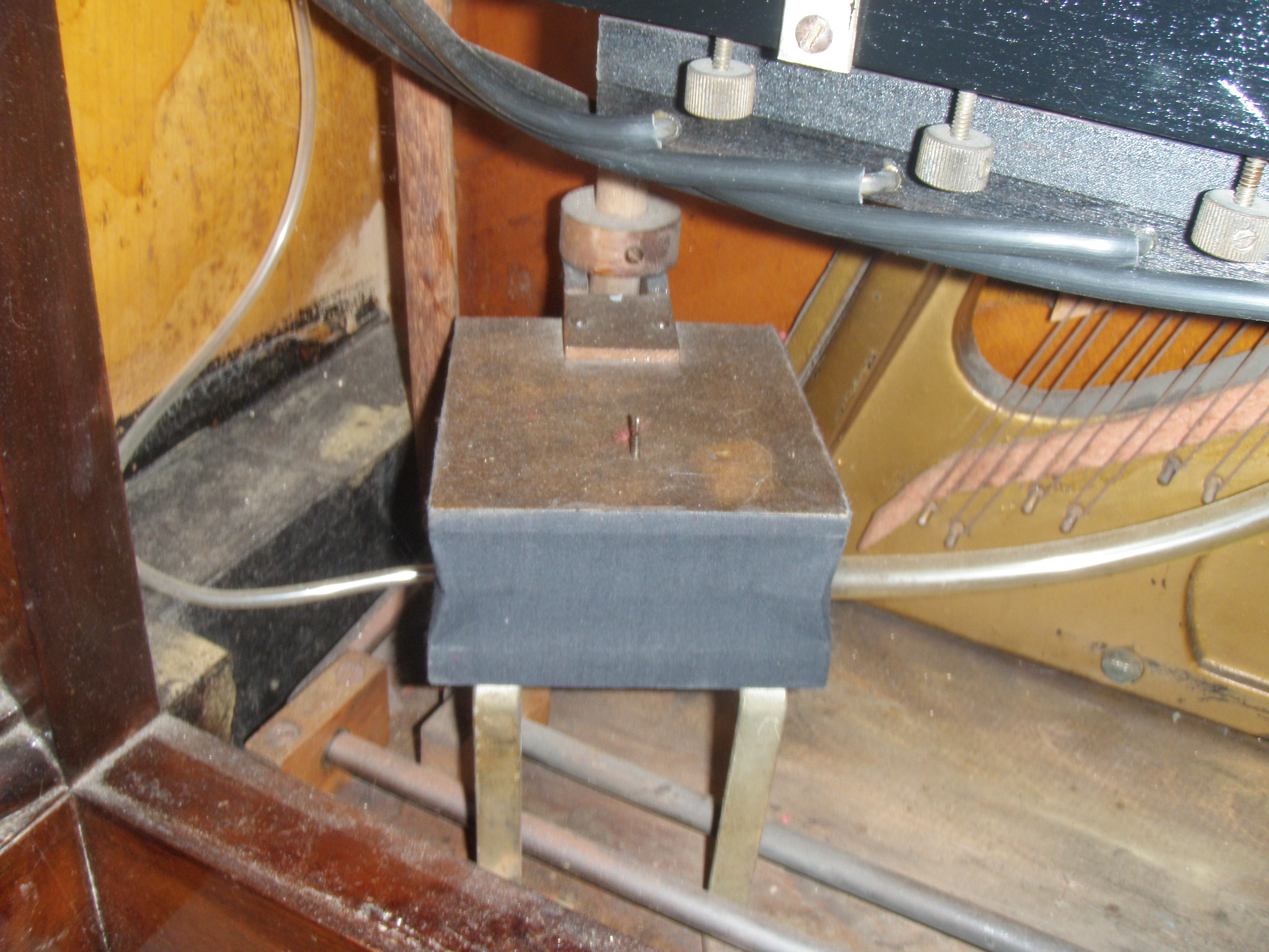
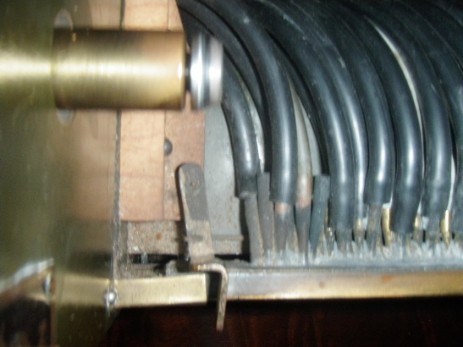
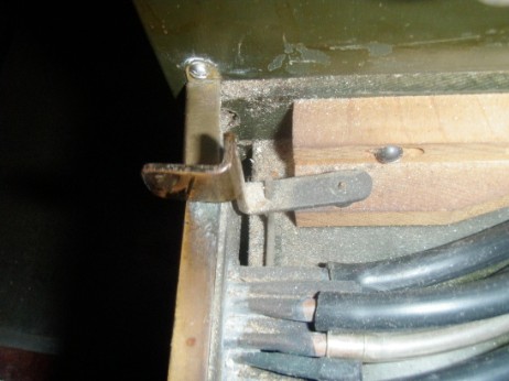
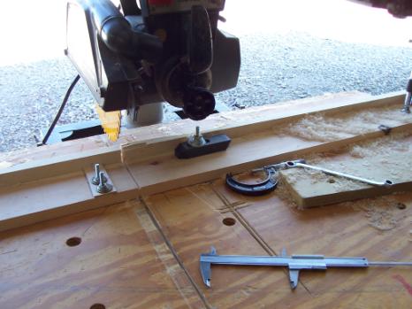
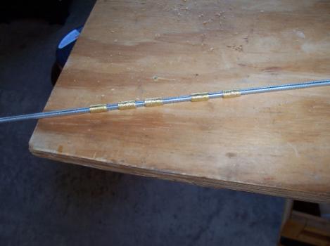
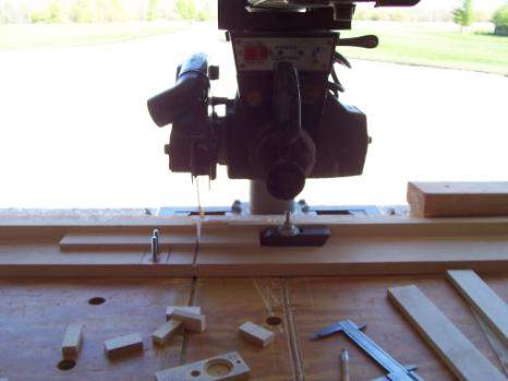
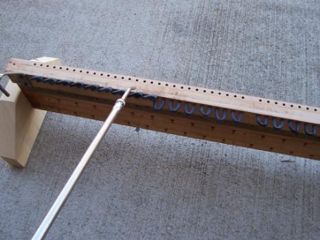
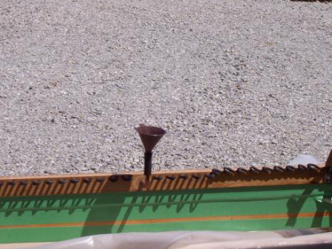
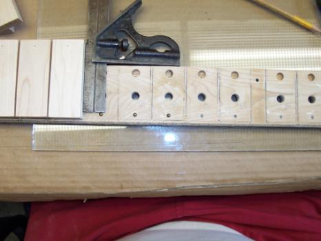
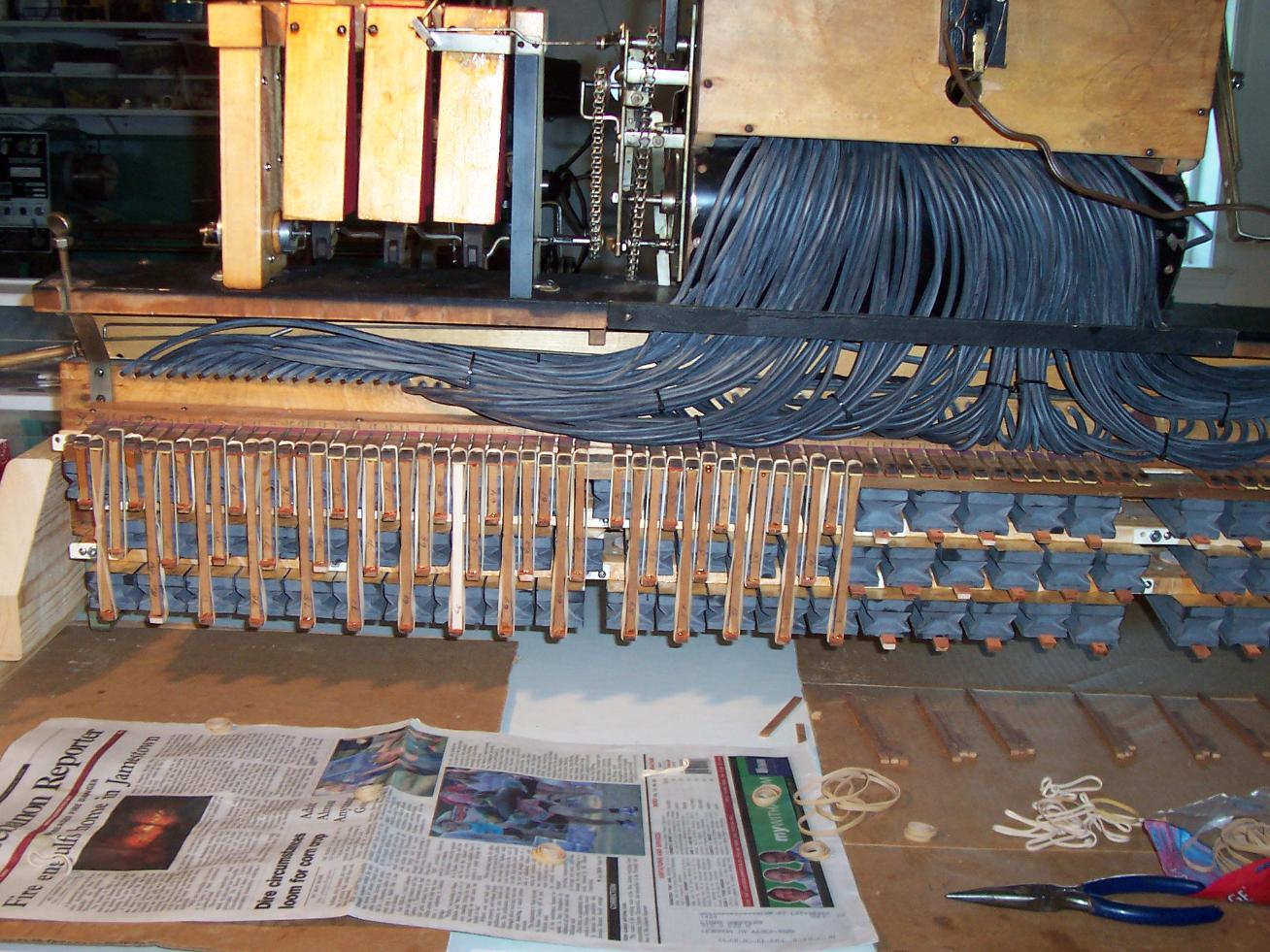
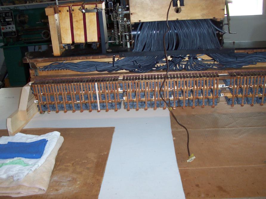
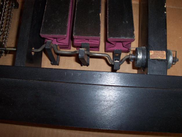
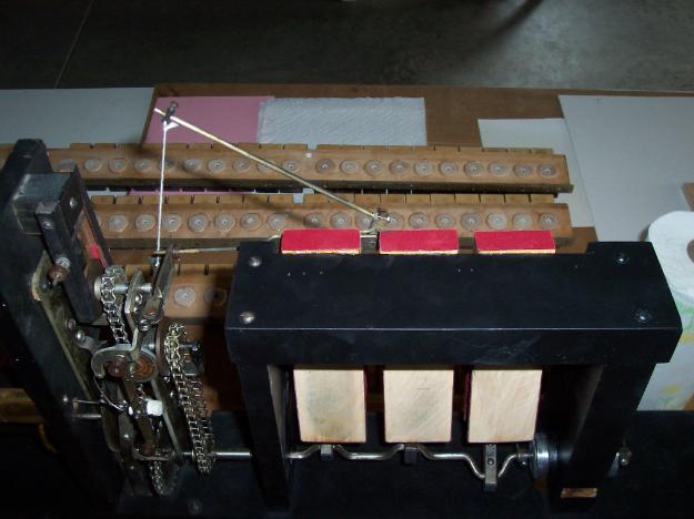
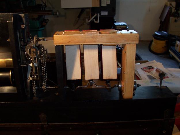
As you can see in the above photo, the linkage starts at the left side stack shut off pneumatic. The linkage is fastened to the stack shut off valve by way of a set screw. The linkage then continues to the right side, where it links the rewind accelerator valve. When the shut off valve is activated by the pneumatic, it opens the right side accelerator valve. When the pneumatic is at rest, the right side accelerator valve is closed, allowing for adjustment of the valve position to closed, via the set screw.
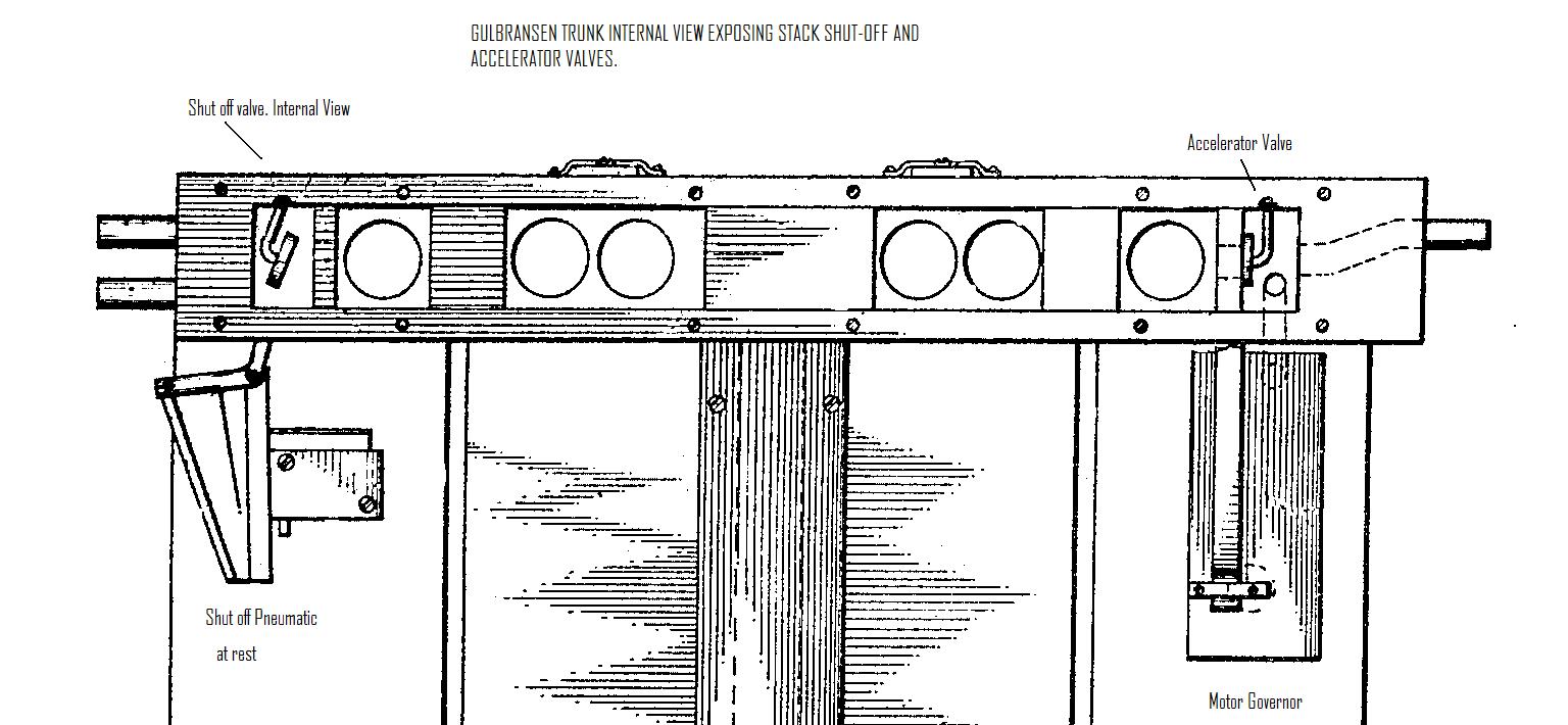
The Gulbransen also features a fast forward control in the spoolbox under the take up spool. By activating this pallet valve (marked 'silent'), the transmission continues in play, but the linkages are activated by the shut-off pneumatic to shut off the stack, and open the accelerator for fast forward. Both of these valves must work in tandem, therefore correct adjustment will result in a properly working machine.

Rare Gulbransen Pedal Grand Piano
Gulbransen Historical Facts by L. Douglas Henderson
Axel Gulbransen went together with a partner and formed the Gulbransen-Dickenson Co. in Chicago around 1904. When they went into players they were OK, but nothing special, sort of a watered down Standard Pneumatic Action (Autopiano) design, as was the Story & Clark series for many years. [The Reprotone was more like a Simplex but with the valves in boards, and very different in design from the older ones. It was part of their 3 piano 'Miniature Player Piano" series which had the pedal player, the Repro-Phraso (pedal/elec.) with manual solo devices, and the Reprotone - possibly a Recordo but I've never seen one advertised. The Repro-Phraso might have had the Recordo on the electric versions of that style.]
They coined the word "Registering" piano to make it sound like "Reproducing" and with an 80 key action, they could play Ampico rolls, for example. (My 1929 Reprotone has a cutoff system: 3 keys for "reproducing" rolls and 5 keys for full "88-Note" rolls.) The valve boards of the Gulbransen-Dickenson lines were changed to unit valves, and there were 2 years (when most were sold) when Gulbransen stacks were glued together. Supposedly, you could buy a replacement stack from inventory until about 1940, piano men once told me - and not bother with re-building. After the glued together line ended, around 1925, the same player re-emerged, but with removable unit valves. Most surviving Gulbransen players here are the early style - mentioned - or the removable unit valve kind.

A Gulbransen Restoration In Indiana
(Following the re-building of a Gulbransen glued stack- step by step)


One of the most difficult restorations in the player world is the early Gulbransen glued stack. But not impossible as proven by Mike from Indiana, who is in the midst of the second restoration of his Gulbransen glued stack. Mike first restored the player 37 years ago, and following advice at the time, used polyurethane for pouches. The urethane has failed, and it's now time to restore again. As you will see from the following pictures, Mike has a terrific workshop facility, and carries out very fine repair and restoration of his player piano. As Mike explains:
Gulbransen still an entertainment centre that fits well in all modern decor's. I like Mike's roll cabinet, I may have to steal that idea.
A fine example of how all workshops should be; neat, well set-out, clean and functional. Plenty of storage and arm-room for working on the benches.
Pneumatic boards separated, waiting sanding for unit re-installation.
Pictures of a fixture Mike made to cut striker pieces - I cut the 1x2 length's to 11" each and then ripped to size (thickness) and then cut to length & width.
Cutting new striker boards.
Drilled pouch well and drilling new bleed.
When I did the first rebuild 37 years ago the only book I had recommended breaking the tier boards off the main supply board - I see most re-builders recommend sawing the main supply board now. Again, hindsight is 20/20. The top tier board did splinter a bit on the mounting edge when first removed so I had a local cabinet shop run it over a jointer taking about 3/32" off the splintered edge. The gasket you see is glued to this main board and the top tier board will have one on it too (2 gaskets making up for the lost edge). I also had drilled 4 additional holes in each tier board for 4 extra mounting screws on each tier to make sure they were tight and seated well. These extra 4 hole along with the 3 original on each tier were all used with long metal screws - you know, I never understood "tapered" wood screws!
Looking at the mounting hole towards the bottom center of picture, looking into the hole you can see the side of the vertical supply channel that is exposed.
The main supply board mounted over the peg. The drill press stop is set to drill a .250" hole .5" deep only, which is roughly half way from the supply holes to the bleed holes. Bleed holes are smaller diameter and survived the 3/16" mounting holes.
One hole drilled for the brass sleeve and you can see the breakout is a bit bigger.I don't believe the supply holes will be reduced enough in cross section to affect the air flow. The tier boards also have the main vacuum channel sawed along their mounting length to allow other holes to help supply vacuum to other strikers.
The 5 each, .5" long brass sleeves with their outside surfaces roughed up.
The top edge of one of the sleeves - I used a small screwdriver this time to point at it. The 5 sleeves were each coated with a thin film of epoxy along with the insides of the wood holes and then pushed in place, level with the top of the wood and well below the gasket surface.
The remaining 2 mounting holes on this top tier were at the ends and well away from the supply/bleed channels. The second tier board down is in a "little" better position to survive these extra tier holes. I will inspect them closely and may use sleeves here too to make sure!

One of the 2 pieces of hard maple ready to be cut to 12" lengths, seems like I've done this before?.
(Mike had to re-make the pouch boards, as the first set was a little too porous in nature, and was difficult to seal without too much seepage. Hard or 'Rock' Maple is recommended)

The new pieces being cut to length and they will be cut to width with the same set-up.

One of the tier boards having its edge cleaned up on the jointer. Not shown, but very important, I put new blades on the jointer first, that was overdue anyway, and blades were very carefully adjusted. Not a place to take any chances!

New pieces ready for drilling pouch & bleed hole etc. Done this before too??
We live less than 100 miles from the old Gulbransen Factory location in Chicago. I know they shipped pianos all over the world. I do still see some for sale around our area but many do not even have the player still in them. If mine is still around in 70 or 80 years, I know I will not be. I would like to think someone would rebuild it again at that time. Likely hood is not on my side, however I would want to think it at least would have a chance. Hard maple pneumatics and the correct glue used this time will give it a better chance.
Several pneumatic pieces being heated prior to sizing.
Pieces are sized with a very thin mix of hot glue and set on small wood pieces to dry. Parts laying on the upper section of the action are already dry.
All pieces were lightly sanded, on a flat surface, to remove any wood fibers that raised due to sizing. The 4 edges were also lightly sanded.
A drill bit in a pin vise was used to clean any plugged bleed holes that had sizing in them. These were all new wood pieces so I put a thin sizing coat on all surfaces that were to be hot glued to another surface. I know hide glue will not adhere to shellac and other finishes so pouch wells and mounting ledges were also sized.
These are hardwood toy wheels that I ordered to replace the valve covers. I was going to make my own, but a web search for wooden washers had these pop up from craftparts.com. A bag of 100 was $6.50. Shipping however added another $8.95. Still cheap I thought and very close to original covers.
I used lacquer thinner to remove the old glue and leathers from the valve lifter discs and this shot shows them being sanded a little to clean up for new leather.
The main stack having air blown thru it to clean out dust etc. before sealing with shellac. Also shows small pieces of tubing from bleed to bleed for shellac sealing step. You can also see a one of the temporary mounting feet attached to the ends of the stack to enable working on it easier.
The 3 tier boards with thru bolts sticking thru - just to make sure all holes are aligned for thru bolts. I want to make sure everything fits "before" final assembly when pneumatics are glued on.
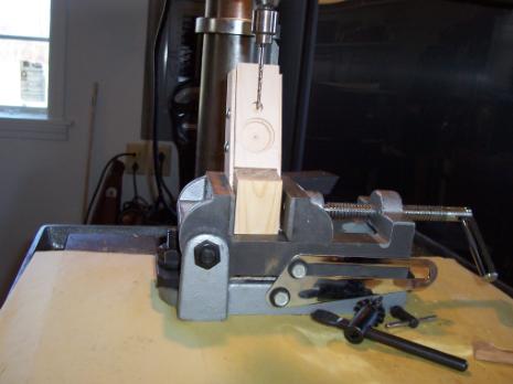
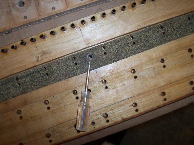
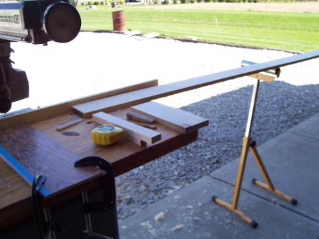
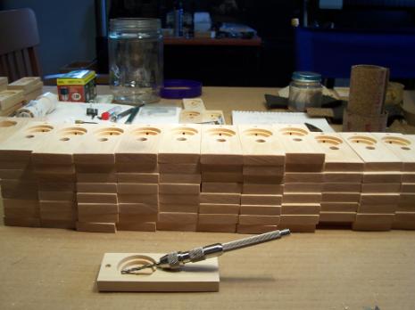
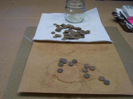
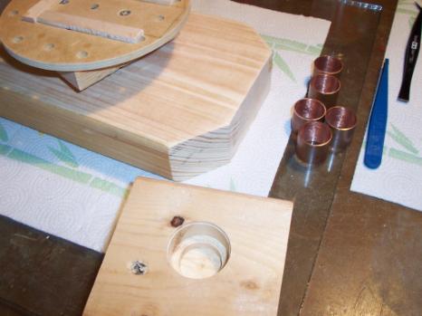
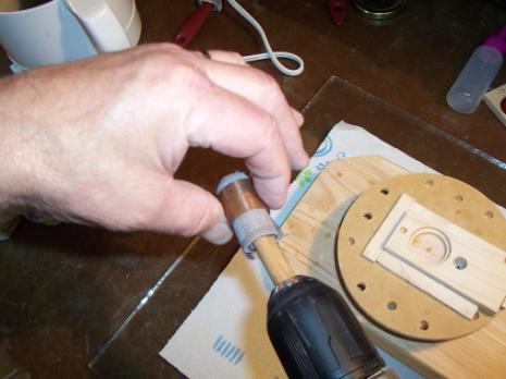
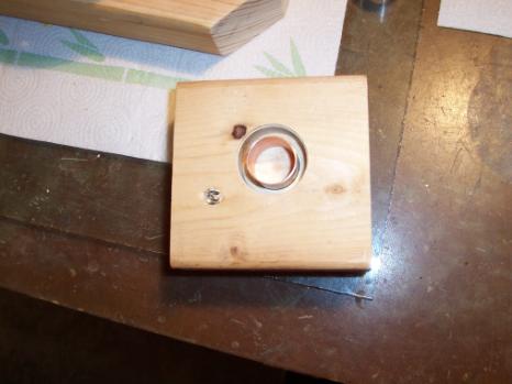
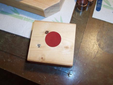
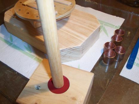
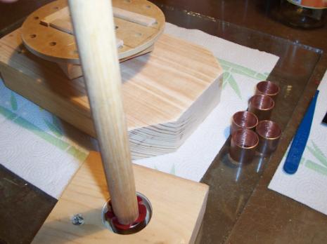
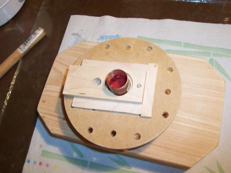
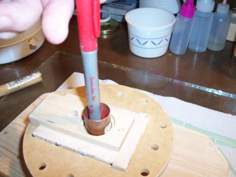
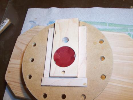
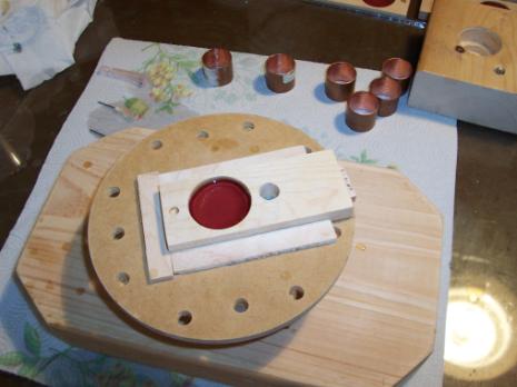
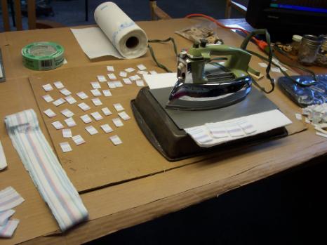
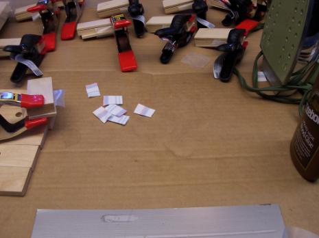
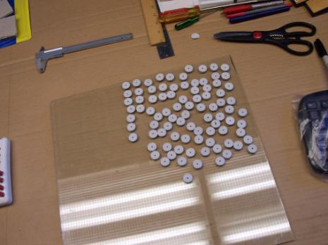
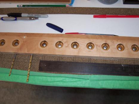
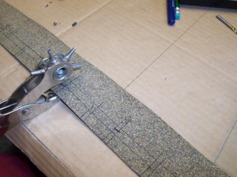
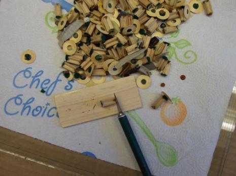
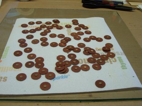
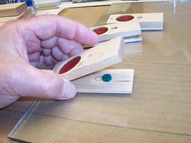
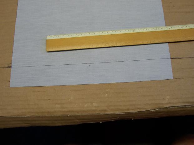
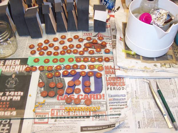
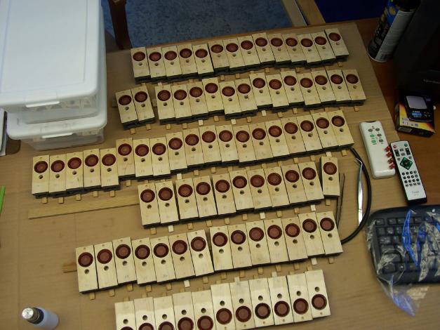
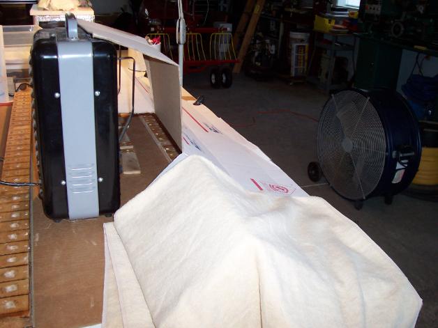
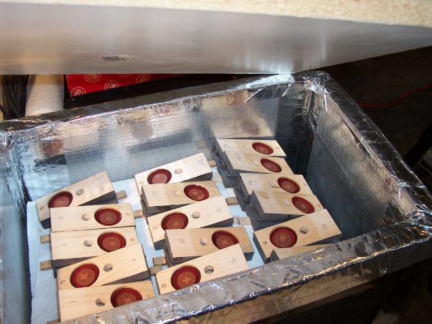
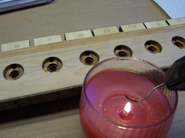
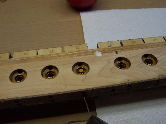
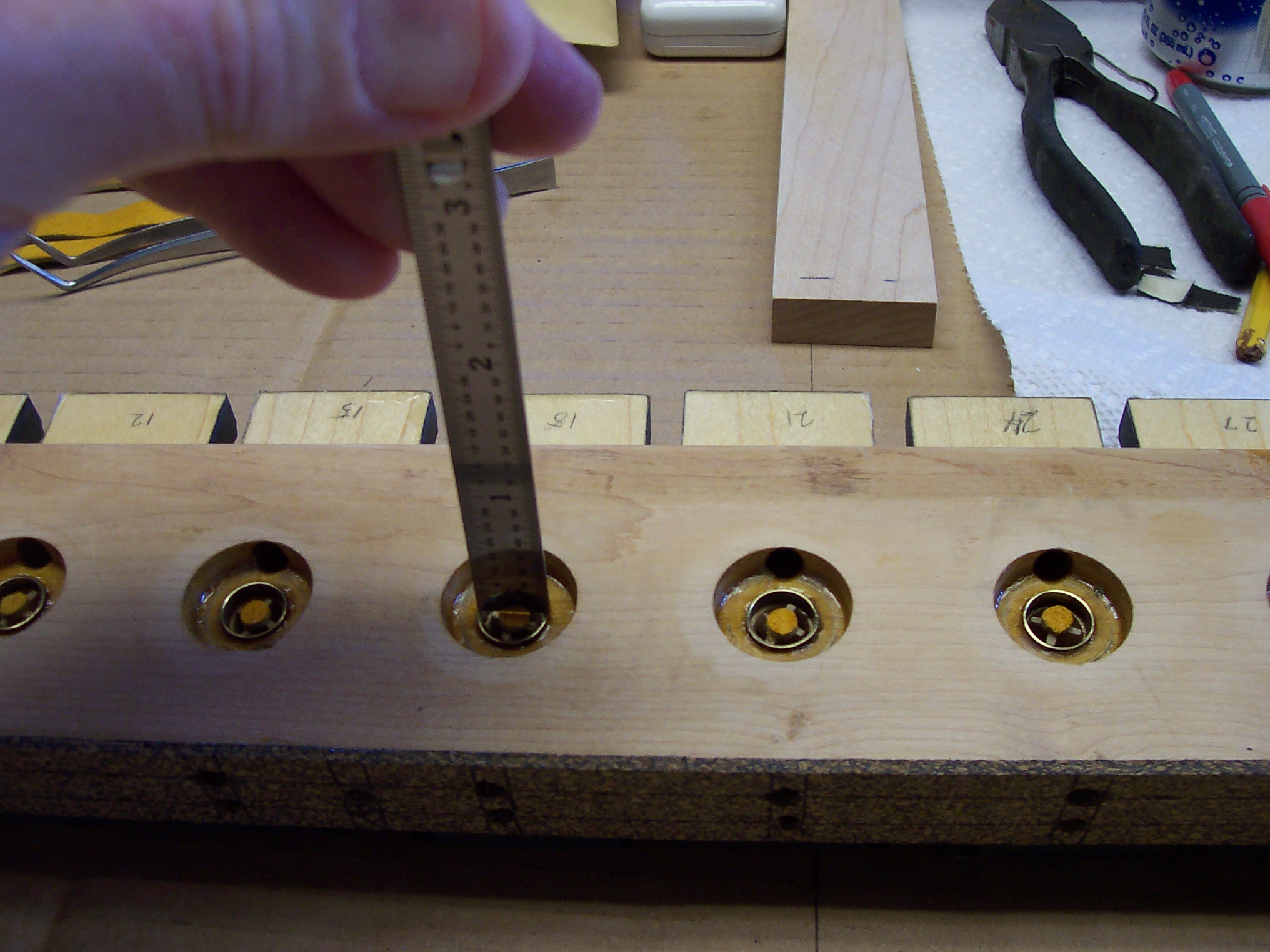
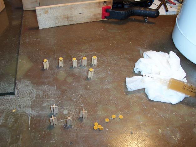
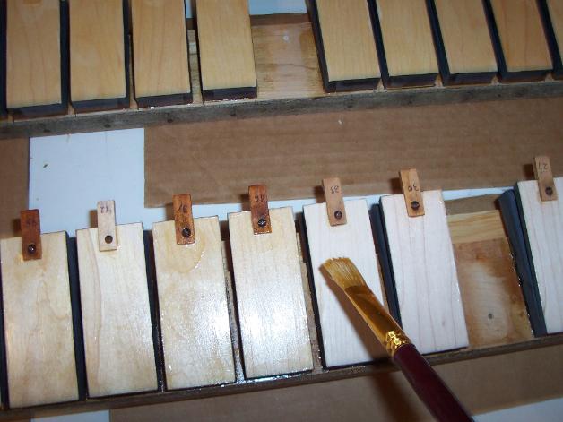
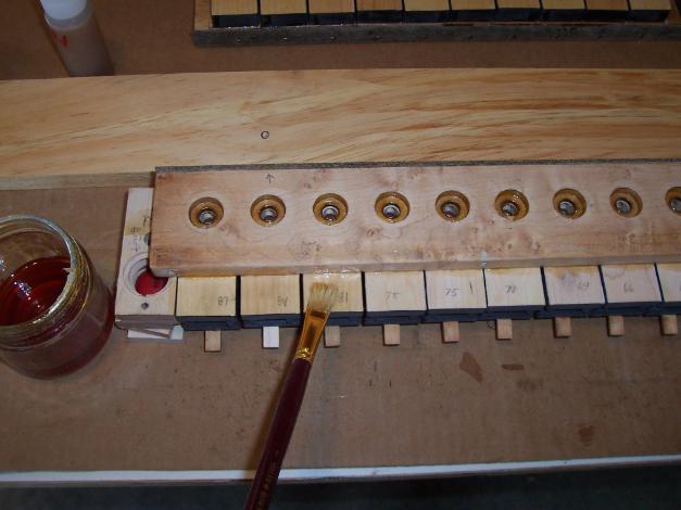
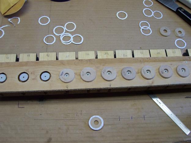
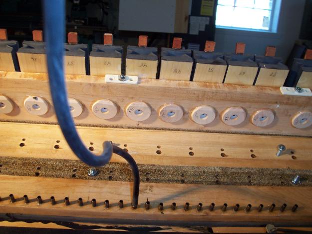
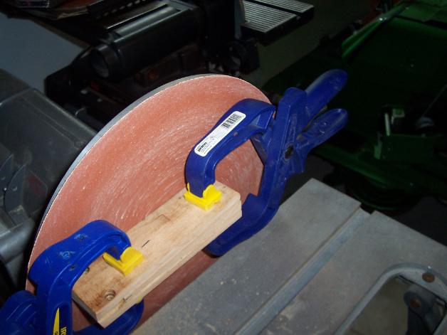
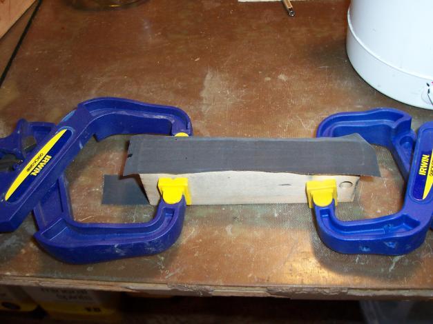
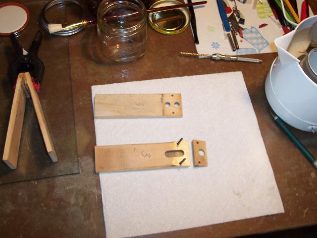
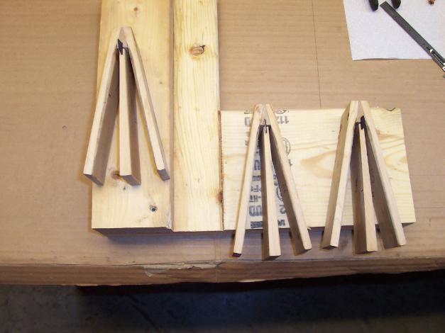
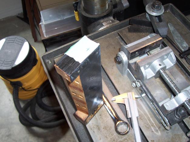
Mike has developed a simple and extremely effective method to set pouches, as set out below:
I drilled a scrap piece of lumber to hold a short section of 3/4" copper pipe at its bottom, a bigger hole the rest of the way up and a shallow hole the same diameter as the pouches at the top. 5 pieces of the copper are shown behind the wood block.
A piece of emery cloth in a short dowel rod used to polish the insides of the copper pieces. Hard to see in picture but the edges of the pipe pieces were also very well smoothed.
One of the copper pieces setting in the bottom hole. Exact dimensions not critical but the top of the copper pipe is just below the top of the wood.
A pouch laying over the pipe and inside the shallow hole for it.
A 1/2" dowel rod ( bottom edge sanded smooth) over the pouch.
Pouch at the bottom of the pipe. It's a loose fit in the pipe but its folded edges hold it inside just fine.
6 pouches loaded and ready to install.
A pouch inside a pipe and setting in the well & ready for the pipe to be pulled up. Note there is no glue in the edge of the well yet. There will be but I couldn't glue and hold a camera at the same time. The pneumatic wood is setting on a small fixture I made to rotate the wood while using a syringe to put glue around the edge of the well. My wife has an old "Lazy Susan" in the attic but I knew I could make one before I ever found hers! I'm sure the whole thing looks like over-kill. I tried brushes and squeeze bottles and this worked the best for me. I have no doubt there are easier techniques - Again, this worked best for me. I liked this way as I could hold the syringe steady while turning the wood piece to spread the glue.
(Doesn't look like over-kill to me, I think the factory would have snapped you up to streamline production, had you been around in the '20's - Paul)
The pouch pretty well spread out in the well.
A glued pouch.
An ingeniously simple and inexpensive method to build and centre perfect pouches. The result speaks for itself. I thank Mike sincerely for sharing his step-by-step photos and captions. I will certainly be giving his method a work-out. -Paul
Cutting and ironing pillow ticking for pneumatic hinges.
Starting to glue on hinges. I used liquid hide glue for these. Gave me a bit more time to align both wood pieces and clamp with waxed paper between hinge halves. Pieces of scrap wood is shown on one side to keep clamp jaws away from new pouches.
This shows the trunk board ready for re-sealing with shellac. Also need to mention the trunk was set on a level surface. Short pieces of old tubing were used to jumper brass nipples, masking tape over holes and a bent piece of copper pipe with a funnel to pour shellac in. Tape leaked, major flood, so a strip of tape was put over the top edge holes, the truck laid over on its back, the funnel and bent copper pipe removed and the funnel used to pour shellac into the trunk. Tier side tapes were all removed and shellac could be seen filling all holes. Trunk was stood up, draining shellac and then hole blown out with compressed air. Before any of this was done, two heavy coats of sizing glue were used on the top edge of the trunk. Denatured alcohol was used to clean exterior surface after draining. In clean up, this top area was sanded to remove any shellac coating so hide glue could be used on new sealing covering.
Top side valve facings glued on and a black dot put in center to help center valve cover later. Roughest side of leather facing up for this side. Bottom leathers have smooth side down and were glued at the outer edges only.
Cork/neoprene gasket being marked for holes.Drill bits used to locate sides of holes and horizontal lines drawn for punch locations. Burnt shellac has not been used to seal valve seats yet and a couple of seats are seen as missing. These will be glued in place with burnt shellac soon.
This shows holes being punched in gasket, using the same punch I bought 30+ years ago for the first rebuild.
A few new pneumatics just setting on a tier board. A square used to locate them and then a line drawn around the new pneumatics. Old partial lines were from the first rebuild. Note BB's setting in bleed holes. I used this idea from another re-builders site and its a great way to locate the pieces.
Old valve stems cleaned of old buckskin and lifter discs. Shown are the discs recommended by PPC for the urethane pouches on the first rebuild.
These are the very original lifter discs that I had kept all these years and they now get a chance to live in the same piano they started life with.

The new tier gasket was glued to the tier board and temporally mounted in place to let the glue dry. I used PVC-E glue for this. It gave me enough time to apply it and mount the tier board before the glue dries. The old gasket was glued with PVC-E and I found lacquer thinner is a great remover of the same.

Showing a felt bumper pad in a pneumatic. The circle was made with a pencil thru the 3/8" port to make sure the felt wasn't directly over the hole. The felt is in the center of the width and far enough from the open end to keep the new covering from having its folds pinched when collapsed.

Line drawn across new bellows material and ready to cut. I did try tearing the first piece and didn't like the result so scissors were used for the rest. Much slower though.

Pneumatic strikers being recovered. Actually I guess just covered without the "re". These were all new wood. I trimmed the cloth before the hide glue dried completely. Then, let them dry overnight.

I glued the hinge end the next day and let that dry before trimming.

I'm reusing the original lifter discs. However, some of the original buckskin punchings were loose so I decided to remove all the old ones and glue on new ones.
Lifter discs glued to pouches. All discs have new buckskin punchings glued to them and then glued to pouches with a very small dot of hot hide glue.
This looks a bit dangerous and is. It worked great but I made sure the heater was ONLY ON while I was in the shop and watching it with extinguishers close at hand. Basically just a hot box to pre warm the tier boards for gluing on pneumatics. tier board ends can be seen thru opening in cover.
A few pneumatics being warmed in the heat box. New ones were put in heat box as ones were taken out to be glued on.
Some pneumatics glued on. The piece of rubber tubing was used to gently blow in the bleed hole to ensure hide glue did not clog holes. The small curved piece of wire was used to clear holes if needed.
New piece of pneumatic cloth glued over holes in top of main trunk. I removed the old piece earlier. It looked OK but getting far to old to trust.
I checked each bleed channel, while gluing pneumatics on the tier boards, and all bleed channels were clear of glue. I checked them again before stems were glued in and did find 1 channel on each of the tier boards that were clogged. Likely I should have let the glue set a bit more before my first testing. A short piece of curved wire was heated with a candle and poked thru the tier hole into the pneumatic hole and wiggled around. Worked great.
I dropped valve stems in all stem holes and checked each for clearance to the top of the brass valve seat. Making sure all were just barely below the edges of the seats. You can see a small air gap above the buckskin and the flat edge of a scale setting on the brass seat. Not shown, several stems needed the buckskin shaved off a bit to get clearance. Each stem was then removed one at a time, a small spot of glue put on the bottom of each and dropped back into its hole, slightly pushing down to insure glue contact with the pouch disc.
Below: a few stems with new buckskin glued on the top end.
Pneumatic boards being sealed with shellac. These external areas were shellaced after cloth glued on and pieces glued to tier boards - just to make sure I didn't get shellac on areas to be hide glued.
Valve covers being glued on. Thickness of each first measured & written on top. Then each held down over its valve and the distance measured from top of washer to valve face. That distance minus cover thickness equals clearance. All were set to .030". A lot of ways to do this, method not important but valve clearance is important.
I brushed a thin coat of pure silicone grease thinned with MEK, "NOT RTV", to tier board gaskets facing main stack.
One tier board mounted back on main trunk. Small pieces of white painted steel straps are shown under two of the tier mounting nuts. These were used under all nuts to spread force and keep nuts from digging into wood. Three bolts shown in unmounted holes were just temporary to check hole clearances. Black tubing on one bleed hole was used to puff air into each hole and check operation of valve and any blocking of pouch air supply.
All tier boards mounted back on stack and ready for push rods.
Pneumatic push rods being Hot Hide glued to new buckskin hinges. Lightly stretched rubber bands were used to hold them together while the glue sets.
Push rods all glued in (light colored one is new piece). Exteriors of motor boards are shown shellaced here. Tracker bar tubing is shown lightly tie wrapped and supported to keep clear of piano action. Electrical stuff is part of electric player pump.
The air motor is shown completely disassembled. some of the pieces simply feel apart after being removed from the support. I put the remainder in the microwave a few seconds and took all pieces apart to clean and re glue. Motor wood pieces were clamped together and carefully sanded to remove all traces of PVC-E that I had used on the first rebuild.
Just to be sure all old PVC-E was removed, I glued a scrap piece of pneumatic cloth to one of the motor sets and let it dry 48 hours before peeling off. From that test it appears all traces of the old glue were removed.
This was the air motor before being removed. Looks don't mean much. It looked OK but material was hard and very leaky. The cloth was hard enough that it make a knocking sound while "trying" to run.
Below left shows a motor glued together and clamped. On the right, screws pushed thru to keep everything aligned when glued.
Motor pieces all glued back together and ready to recover. New hinges were also glued in and all pieces layed on a flat surface to keep everything aligned while drying.
In trying to seal the motor air channels with shellac, I was putting shellac in the top right motor hole shown and found the shellac would just barely pour into the hole. Short hole sections on each end looked OK. So, I drilled a 3/8" hole into the top end aligned with that particular channel. Looking into the channel from the drilled hole I could see a partial plug of old hide glue about 4" down. Hole was not totally clogged and many years ago the motor did seem to work OK. I cleaned it out by using a long piece of dowel rod and glued a short 3/8" dowel piece in the new hole. Then resealed that channel. Not pictured, the vertical leg with air holes was also checked with a bubble jar and one channel had a bad leak. Sealing the holes in the leg took care of that leak. An important point here, on the first rebuild many years ago I know I did not reseal "any" channels in the entire stack. I should have, just didn't. guess I thought if they looked OK they were OK. Wrong. This time I resealed everything!
Motor sections recovered and leather glued on the hinge ends. Top ends were covered in motor cloth.
Wind motor mounted back on stack.
Back to square one with motor. The finished motor did not run well at all. It shows you cannot be too careful with any step. I had sealed all channels with shellac but apparently did not recheck for leaks before assembling motor. So, back apart, channels drilled out and dowels glued in the holes. Some are shown here with pilot holes drilled in dowels. These were drilled to .312" after glue dried. A lot of steps not shown, such as holes drilled to access other holes, plugs and wood epoxy to fill gaps and joints. All passages were then sealed with shellac. This time I triple checked everything before final assembly.
Motor is back together and mounted on stack. I had sealed all motor boards inner faces before covering. Exterior faces will be sealed later. Maple patches shown were HHG back on motor support and SS screws were also added to secure original laminated top & bottom. Motor runs MUCH better this time.
Stack being installed back in piano. The seven black painted steel straps are for the same reason as the small white ones on the back of the tier boards. Two small valve blocks laying at bass end of keys are from the auto rewind pneumatic.
My original goal was to make it as close to original as possible but to also improve what I could without trying to redesign Gulbransen's wheel!
This is the reward; A perfectly restored player piano that is 100 years old and playing as it did when first delivered from the Gulbransen factory. Note repetition is of utmost importance and depends upon the quality of the re-built valves and pouches. This video is an excellent demonstration of everything that you want to achieve when restoring a player piano.*
*Pause the page background music (audio control at bottom of page) to enjoy the performance.
Well it doesn't get any better than this; perfect repetition; uniform and solid note striking; an airtight stack; one of the finest examples of re-building I have ever seen. That it has been performed on a Gulbransen glued stack, notorious as the most difficult stack to restore, is quite amazing. Mike's attention to detail and professional workmanship, has ensured that this particular Gulbransen Player Piano will continue to perform and entertain for many decades to come. I thank Mike sincerely for sharing these wonderful pictures and experiences through the entire process - Paul
September 09, 2012


Finely Made in the USA
Gulbransen serial numbers and corresponding period of manufacture:
1915-90000 * 1920-140000 * 1925-218000 * 1930-301000 * 1935-309000 * 1940-344000Gulbransen branched into the manufacture of organs around 1928, introducing many innovations including transistors in electronic organs in 1962. Gulbransen continues to manufacture quality pianos to this day...
Audio.mp3